CCNA Packet Tracer Labs
Four ready-to-build Cisco labs with diagrams, device configs and the verification idea behind each one.
Lab 01 — VLAN + trunk
Two switches share VLAN 10 (Staff) and VLAN 20 (Guests) over an 802.1Q trunk. Hosts in the same VLAN can reach each other through the trunk. Hosts in different VLANs cannot, because there is no router in this lab.
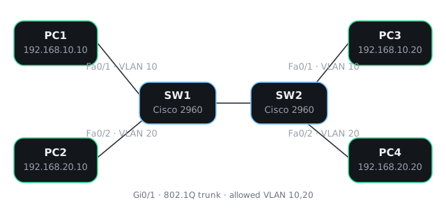
Device configs
SW1.cfg
! Lab 01 — VLAN + trunk
! Device: Cisco 2960 (Packet Tracer)
! Role: SW1, left switch
!
hostname SW1
!
no ip domain-lookup
!
vlan 10
 name Staff
vlan 20
 name Guests
!
interface FastEthernet0/1
 description Access — PC1 Staff
 switchport mode access
 switchport access vlan 10
 switchport nonegotiate
 spanning-tree portfast
 no shutdown
!
interface FastEthernet0/2
 description Access — PC2 Guest
 switchport mode access
 switchport access vlan 20
 switchport nonegotiate
 spanning-tree portfast
 no shutdown
!
interface GigabitEthernet0/1
 description Trunk to SW2 Gi0/1
 switchport mode trunk
 switchport nonegotiate
 switchport trunk allowed vlan 10,20
 no shutdown
!
! On a 3560, add this BEFORE "switchport mode trunk":
!  switchport trunk encapsulation dot1q
! On a 2960 in Packet Tracer that command is not available and will be rejected.
!
end
SW2.cfg
! Lab 01 — VLAN + trunk
! Device: Cisco 2960 (Packet Tracer)
! Role: SW2, right switch
!
hostname SW2
!
no ip domain-lookup
!
vlan 10
 name Staff
vlan 20
 name Guests
!
interface FastEthernet0/1
 description Access — PC3 Staff
 switchport mode access
 switchport access vlan 10
 switchport nonegotiate
 spanning-tree portfast
 no shutdown
!
interface FastEthernet0/2
 description Access — PC4 Guest
 switchport mode access
 switchport access vlan 20
 switchport nonegotiate
 spanning-tree portfast
 no shutdown
!
interface GigabitEthernet0/1
 description Trunk to SW1 Gi0/1
 switchport mode trunk
 switchport nonegotiate
 switchport trunk allowed vlan 10,20
 no shutdown
!
end
Lab 02 — Inter-VLAN routing (router-on-a-stick)
A single physical router interface, with two 802.1Q subinterfaces, routes between VLAN 10 and VLAN 20.
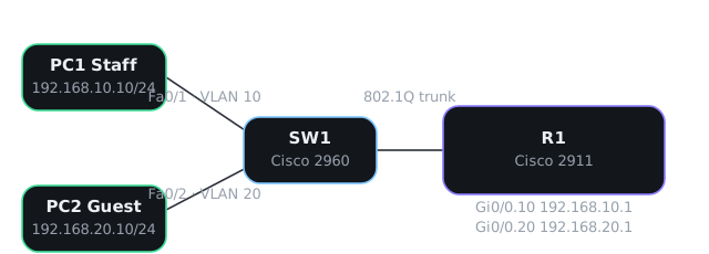
Device configs
R1.cfg
! Lab 02 — Inter-VLAN routing (router-on-a-stick)
! Device: Cisco 2911 (Packet Tracer)
! Role: R1
!
hostname R1
!
no ip domain-lookup
!
interface GigabitEthernet0/0
 description Trunk from SW1 Gi0/1 — no IP on the physical interface
 no ip address
 no shutdown
!
interface GigabitEthernet0/0.10
 description Staff gateway
 encapsulation dot1Q 10
 ip address 192.168.10.1 255.255.255.0
!
interface GigabitEthernet0/0.20
 description Guest gateway
 encapsulation dot1Q 20
 ip address 192.168.20.1 255.255.255.0
!
! Inter-VLAN routing is already enabled: the router has connected routes
! for both subnets and will forward between them.
!
end
SW1.cfg
! Lab 02 — Inter-VLAN routing (router-on-a-stick)
! Device: Cisco 2960 (Packet Tracer)
! Role: SW1
!
hostname SW1
!
no ip domain-lookup
!
vlan 10
 name Staff
vlan 20
 name Guests
!
interface FastEthernet0/1
 description Access — PC1 Staff
 switchport mode access
 switchport access vlan 10
 switchport nonegotiate
 spanning-tree portfast
 no shutdown
!
interface FastEthernet0/2
 description Access — PC2 Guest
 switchport mode access
 switchport access vlan 20
 switchport nonegotiate
 spanning-tree portfast
 no shutdown
!
interface GigabitEthernet0/1
 description Trunk to R1 Gi0/0
 switchport mode trunk
 switchport nonegotiate
 switchport trunk allowed vlan 10,20
 no shutdown
!
end
Lab 03 — OSPF single area
Three routers in OSPF area 0 form neighbours on their physical links, advertise a loopback /32, and can ping each other's loopbacks.
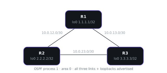
Device configs
R1.cfg
! Lab 03 — OSPF single area (area 0)
! Device: Cisco 2911 (Packet Tracer)
! Role: R1
!
hostname R1
!
no ip domain-lookup
!
interface Loopback0
 ip address 1.1.1.1 255.255.255.255
!
interface GigabitEthernet0/0
 description to R2
 ip address 10.0.12.1 255.255.255.252
 no shutdown
!
interface GigabitEthernet0/1
 description to R3
 ip address 10.0.13.1 255.255.255.252
 no shutdown
!
router ospf 1
 router-id 1.1.1.1
 network 1.1.1.1 0.0.0.0 area 0
 network 10.0.12.0 0.0.0.3 area 0
 network 10.0.13.0 0.0.0.3 area 0
!
end
R2.cfg
! Lab 03 — OSPF single area (area 0)
! Device: Cisco 2911 (Packet Tracer)
! Role: R2
!
hostname R2
!
no ip domain-lookup
!
interface Loopback0
 ip address 2.2.2.2 255.255.255.255
!
interface GigabitEthernet0/0
 description to R1
 ip address 10.0.12.2 255.255.255.252
 no shutdown
!
interface GigabitEthernet0/1
 description to R3
 ip address 10.0.23.1 255.255.255.252
 no shutdown
!
router ospf 1
 router-id 2.2.2.2
 network 2.2.2.2 0.0.0.0 area 0
 network 10.0.12.0 0.0.0.3 area 0
 network 10.0.23.0 0.0.0.3 area 0
!
end
R3.cfg
! Lab 03 — OSPF single area (area 0)
! Device: Cisco 2911 (Packet Tracer)
! Role: R3
!
hostname R3
!
no ip domain-lookup
!
interface Loopback0
 ip address 3.3.3.3 255.255.255.255
!
interface GigabitEthernet0/0
 description to R1
 ip address 10.0.13.2 255.255.255.252
 no shutdown
!
interface GigabitEthernet0/1
 description to R2
 ip address 10.0.23.2 255.255.255.252
 no shutdown
!
router ospf 1
 router-id 3.3.3.3
 network 3.3.3.3 0.0.0.0 area 0
 network 10.0.13.0 0.0.0.3 area 0
 network 10.0.23.0 0.0.0.3 area 0
!
end
Lab 04 — Standard and extended ACL
Standard ACL: block the Guest network from reaching Staff (placed close to the destination). Extended ACL: allow Guest HTTP only to the Staff web server, deny other Guest-to-Staff traffic (placed close to the source). Apply only one variant at a time.
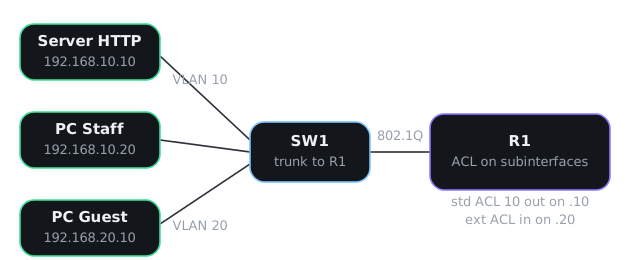
Device configs
R1.cfg
! Lab 04 — Standard and extended ACL
! Device: Cisco 2911 (Packet Tracer)
! Role: R1 — base router-on-a-stick (apply ONE ACL variant, not both at once)
!
hostname R1
!
no ip domain-lookup
!
interface GigabitEthernet0/0
 description Trunk from SW1 Gi0/1
 no ip address
 no shutdown
!
interface GigabitEthernet0/0.10
 description Staff gateway 192.168.10.1
 encapsulation dot1Q 10
 ip address 192.168.10.1 255.255.255.0
!
interface GigabitEthernet0/0.20
 description Guest gateway 192.168.20.1
 encapsulation dot1Q 20
 ip address 192.168.20.1 255.255.255.0
!
end
R1-standard-acl.cfg
! Lab 04 — Variant A: standard ACL
! Apply this AFTER the base R1.cfg (or merge into it).
! Do not also apply the extended ACL at the same time.
!
! Goal: block the entire Guest network (192.168.20.0/24) from reaching
! the Staff network. Place a standard ACL close to the destination:
! outbound on the Staff subinterface.
!
access-list 10 deny 192.168.20.0 0.0.0.255
access-list 10 permit any
!
interface GigabitEthernet0/0.10
 ip access-group 10 out
!
! Remember: a standard ACL has an implicit "deny any" at the end.
! Without "permit any", you would also drop Staff return traffic and
! anything else leaving G0/0.10.
!
end
R1-extended-acl.cfg
! Lab 04 — Variant B: extended ACL
! Apply this AFTER the base R1.cfg. If you tested Variant A first,
! remove it with:  no access-list 10
!                  interface g0/0.10
!                   no ip access-group 10 out
!
! Goal: from the Guest network, allow only HTTP to the Staff web server
! 192.168.10.10. Deny any other Guest-to-Staff traffic. Allow everything
! else (for example Guest to other destinations).
! Place an extended ACL close to the source: inbound on G0/0.20.
!
ip access-list extended GUEST_TO_STAFF
 permit tcp 192.168.20.0 0.0.0.255 host 192.168.10.10 eq 80
 deny ip 192.168.20.0 0.0.0.255 192.168.10.0 0.0.0.255
 permit ip any any
!
interface GigabitEthernet0/0.20
 ip access-group GUEST_TO_STAFF in
!
! Implicit deny still exists, but "permit ip any any" is last on purpose.
! Check hit counts with:  show access-lists GUEST_TO_STAFF
!
end
SW1.cfg
! Lab 04 — Standard and extended ACL
! Device: Cisco 2960 (Packet Tracer)
! Role: SW1
!
hostname SW1
!
no ip domain-lookup
!
vlan 10
 name Staff
vlan 20
 name Guests
!
interface FastEthernet0/1
 description Access — Server HTTP
 switchport mode access
 switchport access vlan 10
 switchport nonegotiate
 spanning-tree portfast
 no shutdown
!
interface FastEthernet0/2
 description Access — PC Guest (VLAN 20)
 switchport mode access
 switchport access vlan 20
 switchport nonegotiate
 spanning-tree portfast
 no shutdown
!
interface FastEthernet0/3
 description Access — PC Staff
 switchport mode access
 switchport access vlan 10
 switchport nonegotiate
 spanning-tree portfast
 no shutdown
!
interface GigabitEthernet0/1
 description Trunk to R1 Gi0/0
 switchport mode trunk
 switchport nonegotiate
 switchport trunk allowed vlan 10,20
 no shutdown
!
end